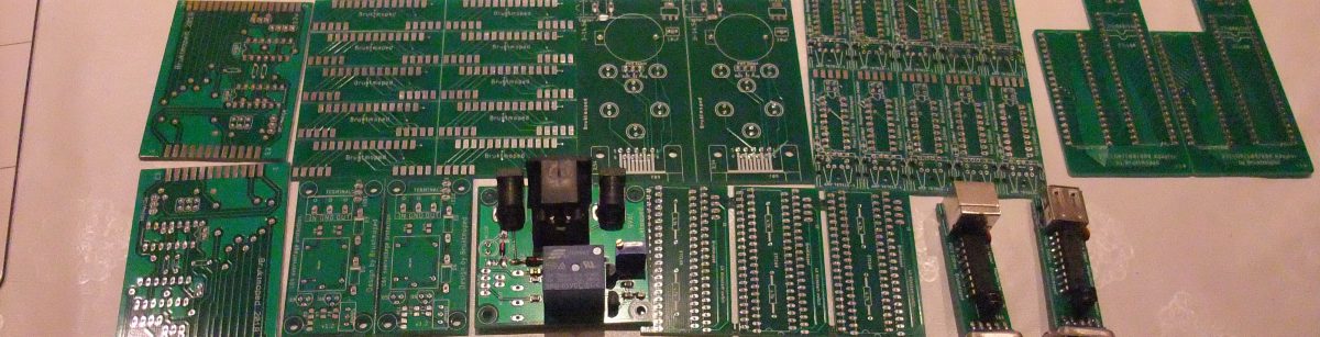
Its always fun to make your own things. This time I decided to make some memorycards for me and a couple of friends. I now have 2 A500 without trapdoor memorycards, because they had battery damage. So instead of buying another old more or less battery acid damaged unstable card, why not make brand new PCBs and solder them for yourself?

For a regular 512k trapdoor memorycard, all you need is:
- 1x 100nF decoupling capasitor
- 1x SOJ42 ram chip.
- 1x 2.54mm 80 pin connector.
- 1x PCB
This particular PCB has been designed to be quite versatile. Besides of being used as a replacement for a simple 512k trapdoor memorycard, for A500 and A500 +, it also can be extended by simply adding one extra capacitor and one extra SOJ42 ram chip, to become a memorycard also for the Amiga 500+, giving the 500+ a total of 2MB chip ram. A few jumpers needs to be connected to hook up the RAS + CAS signals to the other memory bank and to the motherboard connector for this, since the PCB is set as default for being a 512k ram card.
But it does not stop there. The card also can be fitted with a few more parts to also have a working RTC, or real time clock with a modern battery.
On newer revision A500 you can also add a Gary Adapter for upgrading a regular A500 to a total of 2 MB RAM! This however, require some hacking on the Amiga mainboard. When ordering the PCBs I ordered the Gary adapters, but I dont think I will ever use any of them, but they had to be made, right?

The Amiga 500 + Has its own RTC. (real Time Clock) on the mainboard. This is to remember time and date. However, the regular A500 usually had this embedded on the memory expansion board. All the pads for this is embedded in the PCB, but it is totally optional to add the components. This is what you would need to add this feature.
- Parts list for RTC:
- U5 or U6: RTC62421/RTC72421/RTC62423/RTC72423
- R7: 47K-100K 0805 resistor
- C12: 100nF 0805 capacitor
- C13 or C19: >=2.2μF >=10V 0805 or 1206 tantalum
- R1, R2, R3: 10K 0805 resistor
- R4, R5: 220-470 0805 resistor
- D1: BAT721C or BAT54C diode
- Battery Holder
The memorycard with RTC:
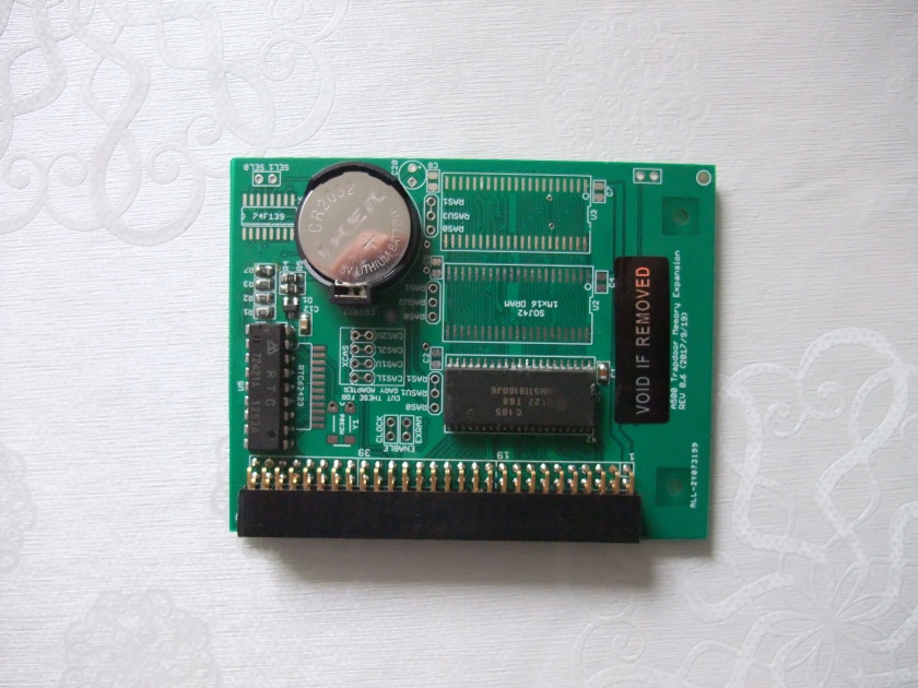
I put a sticker on it after it was tested to remind myself that it’s tested and working.
This is what I do when I build one of these:
I start with soldering the ram chip to U1 using solder paste and a heat gun. I use my multimeter afterwards to verify that all the pins are connected and not shorted. Then I solder the 100nF decoupling capasitor to C1 using solder paste and heat gun. If I want to add the RTC feature, I do those parts before the connector, since there are plastic parts on it. The connector needs to be cut. It is important to use something sharp. I use my sharpest sidecutter for this. I cut on top of the first pin not in use. This is because the connector tend to break into small parts at the cutting point when cutting this way. If I cut between the last pin and the next, It tends to damage the plastic holding the last pins. Cutting on top the next pins avoids this. I will be discarding the rest of the connector anyways. Im sure using a professional saw or Dremel would cut this much nicer, but I dont have one of those handy.
BOM and instructions:
For 512K:
For 512K:* 1 x 1Mx16bit SOJ42 DRAM
* 1 x 56pin (2×28) 2.54mm double row right-angle header (or 2x40pin and cut it)
For A500+ 1MB:
* one more DRAM
For Gary Adapter:
* more DRAMs (any number you want)
* 1 x 74F139 or 74HCT139 (surface mount)
* 3 x 74F00 (surface mount)
* 1 x 74F74 (surface mount)
* 3 x 3-pin jumper headers
* 3 x jumpers
* 2 x 24-pin DIP sockets
* 2 x round pin strips
* Wires and some 2 and 3-pin 2.54mm connectors of your choice
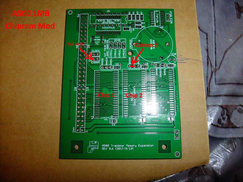
Jumper changes from default 512k:
1MB Chip (A500+):
XRAM: Open
RASU2 to RAS0 closed
512k Chip + 1.0/1.5 Slow with GARY adapter:
RASU2: RAS1,
RASU3: RAS1,
RASU4:RAS1,
XCAS: all open.
This project with PCB and parts can be purchased on ebay: https://www.ebay.com/usr/kirsti_73
Thanks to PeteAU over at http://eab.abime.net for this free PCB design!
